Important Aspects of Electrical Installation Testing
Electrical equipment deteriorates as they age and are used, so it's essential to conduct regular inspection and testing. This ensures that your premises are safe and reduces the chance of fire.
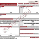 A certified technician will conduct the test using all the necessary equipment. They should issue you with an EICR (EICR) which serves as proof of the upkeep of your electrical domestic installation.
Voltage
Voltage testing is a crucial component of electrical installation testing since it determines the presence of voltage in cables wires, circuit breakers and light fixtures, outlets and switches. It also aids in determining if the device is operating properly.
Testers and meters are diagnostic devices that test the electrical current, voltage, and polarity. They can be used to detect and test for ground faults, identify wire connect types, and assist in locating hot wires.
Multimeters can also be used to test for the presence of stray voltage. This is a voltage that is not reference that results from capacitive coupling that occurs between a ground or neutral wire and an unconnected wire or open connection.
This type of stray voltage is often mistaken for real energized electricity, and it should be identified and corrected right away. If not, it could be hazardous to your equipment and your safety.
A hipot test is utilized to ensure that the flow of electricity does not go between two places when it is plugged in. It also allows you to increase the voltage to ensure that it isn't. Only electrically qualified workers are allowed to test hipot testers to test supply lines with single and three phases.
The first step is to isolate the cable or circuit that will be hipot tested by constructing barriers around the terminations. The limit on approach boundaries for this procedure at 1000 volts is 5 feet. The ground conductor of the hipot tester needs to be connected to the ground of the building or the grounded conductor of the electrode of the circuit phase conductor that is isolated.
Insulation tests are a string of tests to determine the resistance of insulation which is a test of a product's ability to resist the direct current flow of an external voltage source. They are usually conducted using an insulated instrument that can provide a no-load voltage of 500 V or 1000 V if the rated voltage of the insulation system is higher than 500 V.
These tests are usually performed on high-voltage and low-voltage equipment, such as circuit breakers, transformers, switchgear, cables and lightning arrestors. These tests are performed in accordance with the specifications of the relevant safety standard and are often utilized as part of the overall inspection procedure.
Current
The current test uses a meter to measure resistance in an industrial electrical installation circuit. It is used to determine that the circuit is properly connected and will not break under a certain voltage. It can be done by looking at a buzzer or light in connection with the circuit or by taking the resistance between two points.
Continuity tests are the most widely used type of current test used in electrical installation testing. These tests can be conducted in both quantitative and qualitative methods, but they are most effective when performed by a certified electrician.
It is important to remove all outlets and switches from the circuit in order to conduct continuity tests. This will ensure that the test is carried out in a safe and precise manner.
It is also important to remember that when testing a ring circuit , it is essential to ensure that the polarities are correct since polarities that are not correct can result in parts of the installation being connected to a live phase conductor even if single-pole switching devices are off or over-current protection devices have tripped.
An ohmmeter equipped with the continuity function is able to detect incorrect the polarity. An experienced electrician can use it to detect it. The ohmmeter should be set to a low reading, and the tester should be placed between Line and Earth terminals at each outlet of the circuit.
An experienced electrician should ensure that all conductors with protection are connected to the supply Earth by testing the main earthing terminal, as well as the ends of each conductor.
The earthing system is a very crucial element of electrical security and it helps to direct the electrical current towards the ground. It protects appliances and individuals when electrical surges and shocks occur.
It is therefore essential to conduct an inspection and test of all permanently wired equipment in the building before it can be used. This is done by adhering to the testing procedures specified in IEC 60364.6.61, which includes the use of appropriate test tools and safe clothing.
Insulation Resistance
Insulation resistance is a crucial aspect of electrical installation companies installation testing, and a test of the quality of insulation in equipment and wiring. Insulation can prevent short-circuits and electric shocks.
It is vital to regularly test the condition of the insulation used in equipment and wiring to avoid breakdowns. The primary reason is that insulation may degrade over time due environmental conditions like humidity, temperature, and humidity.
The deterioration of insulation causes it to become less robust and less effective at resisting the flow of electricity. This can cause overheating, who installs electric meters (the original source) shocks, and even fires.
This can be prevented by using several tests to determine the electrical equipment's insulation and wiring. These include proof tests spot reading, time resistance and step voltage.
A proof test is the process of connecting a Megger instrument and an item of equipment, and operating the meter over an amount of time. The meter will then display the resistance values on the display and keep track of the results of the measurement.
The spot reading method is also a very simple method of evaluating insulation. Simply connect the Megger instrument and run the device for around an hour. The resistance values will be displayed on the display. You can then take notes at different intervals.
This is among the best methods for recording insulation data because it offers the ratio of two resistance readings. This ratio will reveal if the resistance is decreasing or increasing over time, and also provide a useful indicator of the condition of your insulation.
Another method of measuring resistance is to use the polarization index. It is the ratio between the resistance at 10 minutes and the resistance at one minute. Any value less than 1.0 indicates poor meter insulation. A PI value between 2.0-4.0 is considered good insulation. Anything above 4.0 is considered excellent.
Earth Resistance
Earth resistance testing is an essential part of electrical installation testing, making sure that grounding systems are operating properly, and protecting people and equipment from overvoltages. It also helps identify any problems in the grounding system prior to they become serious.
There are numerous methods that can be used to test earth resistance. These include step and touch potential tests, electrical Installation near me fall-ofpotential and earth coupling tests.
The most common and reliable method is the fall-of-potential test. It is a tested method that is founded on IEEE standards and is suitable for determining the resistance of transmission lines.
It involves the use of a voltage spike and a current test electrode that is placed in the soil at various distances along the straight line. The current is then measured at every distance and the resistance of the electrode in test is determined by using Ohm's law.
This test is a great method to determine the soil's resistance at various depths however it is crucial that you perform this test in a correct manner. The soil's composition as well as the moisture content will impact the results. This is the reason it is essential to consider this when you plan your earthing system.
Another useful way to test the earth's resistance is using the stake-less method which uses a small test meter to connect directly to the ground electrode, instead of a clamp-on tester. This is useful for a variety of purposes such as remote switching offices and cellular towers.
Tests that do not require stakes can be carried out on any surface which makes them suitable for a variety of applications. However, it is crucial to remember that they are not a reliable test to measure resistance to ground, and therefore should not be used in lieu of a fall-of potential method.
The most popular method for testing the earth is the fall of potential method, which uses the use of a voltage spike as well as the current test meter. The voltage spike is inserted in soil at different distances and the current is measured at each location. The resistance of the electrode under test is calculated by calculating the voltage drop and the current that flows through it.
Electrical equipment deteriorates as they age and are used, so it's essential to conduct regular inspection and testing. This ensures that your premises are safe and reduces the chance of fire.
A certified technician will conduct the test using all the necessary equipment. They should issue you with an EICR (EICR) which serves as proof of the upkeep of your electrical domestic installation.Voltage
Voltage testing is a crucial component of electrical installation testing since it determines the presence of voltage in cables wires, circuit breakers and light fixtures, outlets and switches. It also aids in determining if the device is operating properly.
Testers and meters are diagnostic devices that test the electrical current, voltage, and polarity. They can be used to detect and test for ground faults, identify wire connect types, and assist in locating hot wires.
Multimeters can also be used to test for the presence of stray voltage. This is a voltage that is not reference that results from capacitive coupling that occurs between a ground or neutral wire and an unconnected wire or open connection.
This type of stray voltage is often mistaken for real energized electricity, and it should be identified and corrected right away. If not, it could be hazardous to your equipment and your safety.
A hipot test is utilized to ensure that the flow of electricity does not go between two places when it is plugged in. It also allows you to increase the voltage to ensure that it isn't. Only electrically qualified workers are allowed to test hipot testers to test supply lines with single and three phases.
The first step is to isolate the cable or circuit that will be hipot tested by constructing barriers around the terminations. The limit on approach boundaries for this procedure at 1000 volts is 5 feet. The ground conductor of the hipot tester needs to be connected to the ground of the building or the grounded conductor of the electrode of the circuit phase conductor that is isolated.
Insulation tests are a string of tests to determine the resistance of insulation which is a test of a product's ability to resist the direct current flow of an external voltage source. They are usually conducted using an insulated instrument that can provide a no-load voltage of 500 V or 1000 V if the rated voltage of the insulation system is higher than 500 V.
These tests are usually performed on high-voltage and low-voltage equipment, such as circuit breakers, transformers, switchgear, cables and lightning arrestors. These tests are performed in accordance with the specifications of the relevant safety standard and are often utilized as part of the overall inspection procedure.
Current
The current test uses a meter to measure resistance in an industrial electrical installation circuit. It is used to determine that the circuit is properly connected and will not break under a certain voltage. It can be done by looking at a buzzer or light in connection with the circuit or by taking the resistance between two points.
Continuity tests are the most widely used type of current test used in electrical installation testing. These tests can be conducted in both quantitative and qualitative methods, but they are most effective when performed by a certified electrician.
It is important to remove all outlets and switches from the circuit in order to conduct continuity tests. This will ensure that the test is carried out in a safe and precise manner.
It is also important to remember that when testing a ring circuit , it is essential to ensure that the polarities are correct since polarities that are not correct can result in parts of the installation being connected to a live phase conductor even if single-pole switching devices are off or over-current protection devices have tripped.
An ohmmeter equipped with the continuity function is able to detect incorrect the polarity. An experienced electrician can use it to detect it. The ohmmeter should be set to a low reading, and the tester should be placed between Line and Earth terminals at each outlet of the circuit.
An experienced electrician should ensure that all conductors with protection are connected to the supply Earth by testing the main earthing terminal, as well as the ends of each conductor.
The earthing system is a very crucial element of electrical security and it helps to direct the electrical current towards the ground. It protects appliances and individuals when electrical surges and shocks occur.
It is therefore essential to conduct an inspection and test of all permanently wired equipment in the building before it can be used. This is done by adhering to the testing procedures specified in IEC 60364.6.61, which includes the use of appropriate test tools and safe clothing.
Insulation Resistance
Insulation resistance is a crucial aspect of electrical installation companies installation testing, and a test of the quality of insulation in equipment and wiring. Insulation can prevent short-circuits and electric shocks.
It is vital to regularly test the condition of the insulation used in equipment and wiring to avoid breakdowns. The primary reason is that insulation may degrade over time due environmental conditions like humidity, temperature, and humidity.
The deterioration of insulation causes it to become less robust and less effective at resisting the flow of electricity. This can cause overheating, who installs electric meters (the original source) shocks, and even fires.
This can be prevented by using several tests to determine the electrical equipment's insulation and wiring. These include proof tests spot reading, time resistance and step voltage.
A proof test is the process of connecting a Megger instrument and an item of equipment, and operating the meter over an amount of time. The meter will then display the resistance values on the display and keep track of the results of the measurement.
The spot reading method is also a very simple method of evaluating insulation. Simply connect the Megger instrument and run the device for around an hour. The resistance values will be displayed on the display. You can then take notes at different intervals.
This is among the best methods for recording insulation data because it offers the ratio of two resistance readings. This ratio will reveal if the resistance is decreasing or increasing over time, and also provide a useful indicator of the condition of your insulation.
Another method of measuring resistance is to use the polarization index. It is the ratio between the resistance at 10 minutes and the resistance at one minute. Any value less than 1.0 indicates poor meter insulation. A PI value between 2.0-4.0 is considered good insulation. Anything above 4.0 is considered excellent.
Earth Resistance
Earth resistance testing is an essential part of electrical installation testing, making sure that grounding systems are operating properly, and protecting people and equipment from overvoltages. It also helps identify any problems in the grounding system prior to they become serious.
There are numerous methods that can be used to test earth resistance. These include step and touch potential tests, electrical Installation near me fall-ofpotential and earth coupling tests.
The most common and reliable method is the fall-of-potential test. It is a tested method that is founded on IEEE standards and is suitable for determining the resistance of transmission lines.
It involves the use of a voltage spike and a current test electrode that is placed in the soil at various distances along the straight line. The current is then measured at every distance and the resistance of the electrode in test is determined by using Ohm's law.
This test is a great method to determine the soil's resistance at various depths however it is crucial that you perform this test in a correct manner. The soil's composition as well as the moisture content will impact the results. This is the reason it is essential to consider this when you plan your earthing system.
Another useful way to test the earth's resistance is using the stake-less method which uses a small test meter to connect directly to the ground electrode, instead of a clamp-on tester. This is useful for a variety of purposes such as remote switching offices and cellular towers.
Tests that do not require stakes can be carried out on any surface which makes them suitable for a variety of applications. However, it is crucial to remember that they are not a reliable test to measure resistance to ground, and therefore should not be used in lieu of a fall-of potential method.
The most popular method for testing the earth is the fall of potential method, which uses the use of a voltage spike as well as the current test meter. The voltage spike is inserted in soil at different distances and the current is measured at each location. The resistance of the electrode under test is calculated by calculating the voltage drop and the current that flows through it.